Search
Close this search box.

Application

Electroplating With FDM Masters

Bond, seal and beautify 3D printed parts.

Overview

Electroplating deposits a thin layer of metal on the surface of a part built on a Fortus 3D Production System using the FDM process. This metal coating can be both decorative and functional. The coating gives the appearance of production metal or plated parts and provides a hard, wear-resistant surface with reflective properties.

The electroplated part also has improved mechanical properties. With simple finishing techniques, FDM parts are ready for electroplating with alloys such as chromium, nickel, copper, silver and gold. Combining the properties of Fortus materials with those of a metal coating, the part has strength, durability and heat resistance that is ideal for functional applications.

Electroplating For Increased Durability

Electroplating not only enhances the look of a part but it also produces a hard, durable surface and dramatically increases the strength of an FDM part. Electroplating causes a dramatic increase in strength.

The FDM test bars were built both flat and on edge. The plating thickness was tested at both 0.005 inch (0.127 mm) as well as 0.010 inch (0.254 mm). The thickness of plating typically ranges from 0.0001 inch to 0.020 inch (0.0025 mm 0.508 mm). The FDM test bars were plated with a combination of nickel and copper, although typical metals used in plating also include chrome, brass, palladium, silver and gold.

Process

Consult with a Vendor on process specifics, estimate coating thickness, temperature exposed and other variables. Choose the right Fortus material and adjust the part according the vendors specifications.

cad img

Adjust CAD File

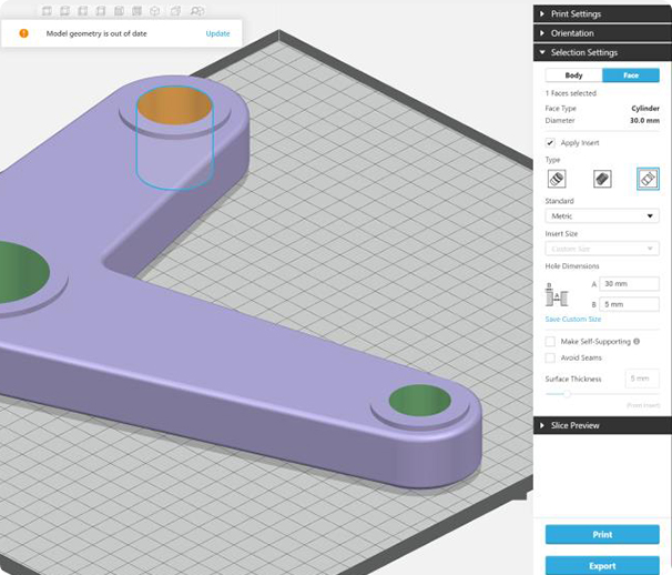
Offset surfaces in the CAD model to allow for the thickness of the electroplated material. If there are any critical dimensions, such as hole or boss diameters, they should be communicated to the electroplater so that these dimensions can be maintained throughout the electroplating process.

fdm part img

Build FDM Part

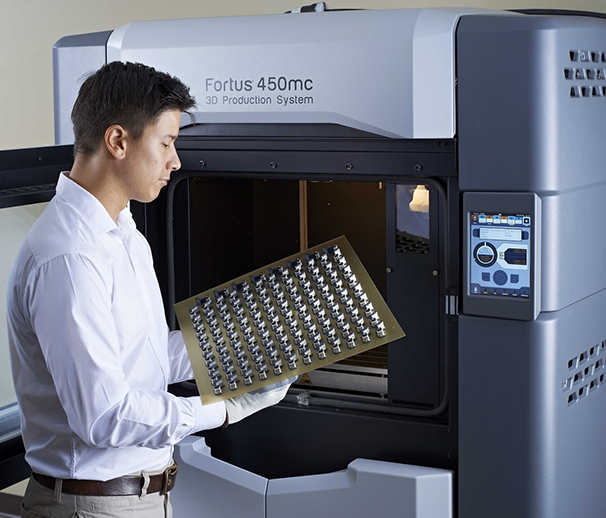
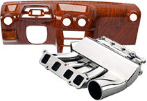
Materials that have been tested include; ABS-M30, ABS, ABSplus. While all other Fortus materials may be suitable for electroplating, they have not been tested at the time of publishing this document.

*NOTE: Parts can be built in either solid or sparse fill.

sand surfaces img

Sand Surfaces

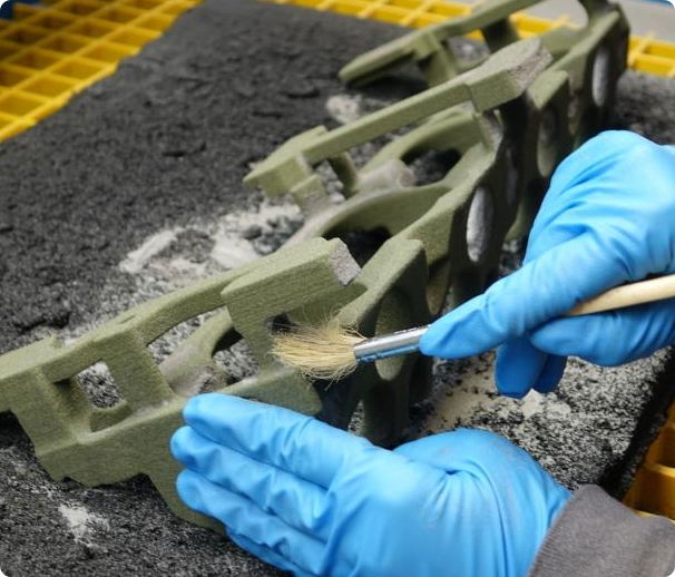
After removing support structures, sand the part to remove build layer lines and stepped areas. At this point, a coarse sanding is sufficient. The smooth surfaces needed for electroplating will be addressed in the next few steps.

Seal Surfaces

The part must be sealed to prevent it from absorbing any of the electroplating solutions. There are three options for sealing the FDM part; smoothing the surface with the Finishing Touch™ Smoothing Station, solvent dipping, and painting.

*NOTE: These methods will also smooth the surface of the part.

Option 1: Finishing Touch Smoothing Station The first technique, smoothing the surface of the FDM part using the Finishing Touch Smoothing Station, seals the surface by exposing the FDM part to a vaporized solvent for 15 to 30 seconds. Smoothing has been tested on ABS, ABSplus ABS-M30, and ABSi.

Option 2: Solvent Dipping The second technique, solvent dipping, seals the surface by submerging the FDM part in a chemical bath for approximately 15 seconds. The recommended solvent is a methylene chloride solution, sold commercially as Weld-on #3 from the IPS Corporation. If this is not available, methyl ethyl ketone (MEK), sold commercially as Weld-on #2354, may be substituted.

Option 3: Painting The third technique, painting, will seal the part as well as fill in the layer lines. Spray the part with sandable primer and allow it to dry. Then, sand the part to the desired finish. Repeat as necessary. *NOTE: Before applying primer, seek the advice of the electroplater. Primers can cause adverse reactions and contaminate the tanks of electroplating solutions. Also, if FDM master is painted the electroplater will need to apply a “spray” conductive coating instead of using the traditional electro-less nickel bath. Putting a painted part into a bath may ruin the bath. Skip to step 7 if using Option 3.

Dry Paint

There will be solvent trapped in the part after the sealing process. If electroplating is attempted before the solvent has completely evaporated, the plating material will bubble and peel off of the part. Allowing the part to dry for a minimum of 18 hours will ensure that no solvent remains. However, the drying time may take longer since it is dependent on the part’s geometry. To accelerate the process, the part can be heated overnight in an oven set to a maximum temperature of 110°F (43°C).

resand surfaces img

Re-sand Surfaces

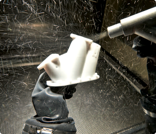
Sand away any remaining layer lines or stepped surfaces with a wet sand paper (500-1200 grit) and repeat steps four and five. Repeat the sealing and sanding steps until the part is free of defects. Minor flaws must be buffed out of the copper coating before the nickel coating is applied.

electroplating img

Electroplating

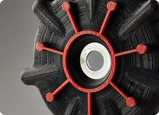
Send part to the approved vendor for electroplating. Verify coating thickness specifications with vendor.

Copper layer thickness guideline: 0.005 – 0.010 inches (0.127 – 0.254 mm) thick.

Nickel layer thickness guideline: 0.001 inch (.0254 mm) thick.

Chromium (Optional) layer thickness guideline: 0.001 inch (.0254 mm) thick.

electroplating sample
modeling img

Request Sample Part

Filter Used 3D Printers

Sort By

Industry
Industry
Application
Application
Technology
Technology
Material
Material
More
Printer Size
Printer Size

Filter 3D Printers

Sort By

Industry
Industry
Application
Application
Technology
Technology
Material
Material
More
Printer Type
Printer Type

Get Free Quote

Contact Us

Enquire For Price